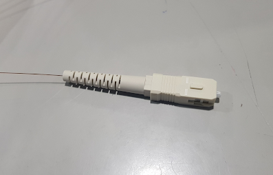
In this post I am going to do a hand termination of a Single Mode SC (Standard Connector).
Following are the list of tools and materials used.
1. Dintek Fiber Toolkit (Stripper, Scribe tool, Syringe, Polishing papers etc)
2. Dintek SC connector
3. LOCKTITE 680 & LOCKTITE SF 7649 Glues
4. Surgical sprite
5. Fluke Fiber Inspector
Step 01
Strip out the fiber cable gently using the cable stripper tool in the toolkit.
There are 3 slots in the cable stripper tool.
Use the largest slot to strip the buffer jacket (blue rubber case in the picture) and use the smallest slot to peel out the buffer coating.
Cladding (transparent, human hair thin glass) should be then cleaned by surgical sprite using a tissue paper.
(click on the image to view in full size)
Note that you will need to strip out the outer hard jackets like armored layers in practical situations with different cable types. Use the necessary tools with care to reduce the damage to the fiber and yourself.
Anyhow you must clean the cable up to the cladding in order to do the rest..
Standard color code pairs used by most passive engineers for terminations are like in the right side image..
This is for a regular 12 Core fiber..
Step 02
Unpack and take out the connector parts from the packet and insert the cable through the boot and then insert the middle band like in the picture.
It is always a best practice to remove the dust cap of the connector and try inserting the fiber through the connector until it comes out from the other side to test the connector without glue because some connectors may have a block in the hole.
Step 03
The glues I am using are LOCTITE 680 and LOCTITE SF 7649. When these 2 glues are mixed together it will be a cement.
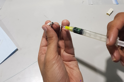
Put LOCTITE 680 (red bottle) in a syringe and inject the gum into the connector until you see a dot comes out from the other end.

Step 04
Spray or coat LOCTITE SF 7649 around the fiber cladding and insert it through the connector until it comes out from the other end. You must do this quickly to avoid the fiber stick in the connector because of the mixing of 2 glues, but gently to avoid it from breaking..
Keep it for 30 seconds to fix the glue..
Step 05
Now use the Scribe tool (pen like silver color tool with a sharp edge at the end) to cutout the fiber gently. Be careful to use it in a 90 degrees angle with the fiber and be sure to cut the fiber with a zero length out from the connector end. Also be sure to scribe not to break..
Step 06
Use the brown fiber polishing paper to polish the surface of the connector 1st. Use your hand with number "8" movement as shown below. This should be done with extreme care and slowly..
Note that in the picture, it looks like both my hands are moving because of my lack of experience. But it is better move the paper only while holding the connector still.
The Brown, Green and the White papers are mostly the standard papers used in the industry. The polishing order is chosen from roughest to softest.
Step 07
Now put the rubber board in the toolbox on the glass and pour bit of water on to it. Then get the green polishing paper and put it on the rubber board.
The paper will stick to the board and use the "SC/FC" connector holder in the toolbox to hold the connector and start polishing the surface with number "8" movement.
Start slowly and speed the movement slowly..
Step 08
Now use the white paper to do the same with and continue it until your hand does not feel the tip of the fiber..
After polishing, make sure to clean the surface with a tissue..
Step 09
Now use the Luk tool (Fiber Crimp tool) in the toolbox to crimp the middle band with the connector and fix the boot and outer case of the connector to complete the termination..

Step 10
For the final testing of the connector-end, I am using Fluke Fiber Inspector tool. You can use the magnifying glass in the Dintek toolbox for this too but Fluke Fiber Inspector is much more reliable..
(click on the images to view in full size)
Insert the connector end to the tip of the camera and select the Fluke Fiber Inspector from the menu.

It is better to check the loss of the fiber by doing a quick audit using Fluke tester after you done with both the ends.


No comments:
Post a Comment